The structural analysis software RFEM 6 is the basis of a modular software system. The main program RFEM 6 is used to define structures, materials, and loads of planar and spatial structural systems consisting of plates, walls, shells, and members. The program also allows you to create combined structures as well as to model solid and contact elements.
RSTAB 9 is a powerful analysis and design software for 3D beam, frame, or truss structure calculations, reflecting the current state of the art and helping structural engineers meet requirements in modern civil engineering.
Do you often spend too long calculating cross-sections? Dlubal Software and the RSECTION stand-alone program facilitate your work by determining section properties of various cross-sections and performing a subsequent stress analysis.
Do you always know where the wind is blowing from? From the direction of innovation, of course! With RWIND 2, you have a program at your side that uses a digital wind tunnel for the numerical simulation of wind flows. The program simulates these flows around any building geometry and determines the wind loads on the surfaces.
Are you looking for an overview of snow load zones, wind zones, and seismic zones? Then you are in the right place. Use the Geo-Zone Tool to determine quickly and efficiently snow loads, wind speeds, and seismic data according to ASCE 7‑16 and other international standards.
Would you like to try out the capabilities of the Dlubal Software programs? You have the opportunity to do so! The free 90-day full version allows you to thoroughly test all our programs.
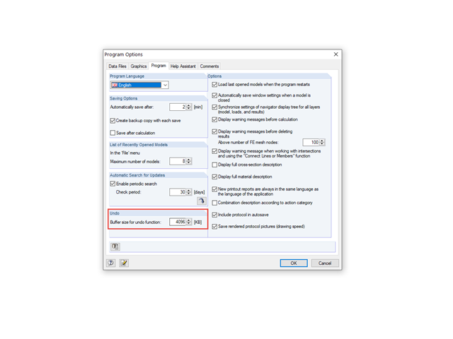
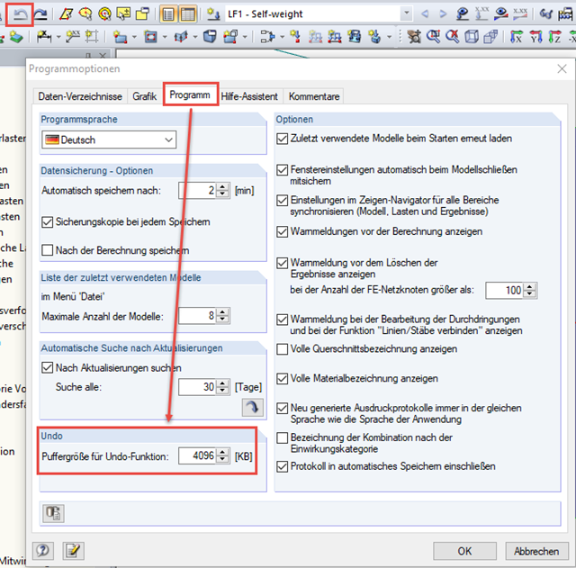
To set the size of the buffer memory for the undo function, open the Program Options dialog box using the Options menu.
In the "Program" tab, the Buffer size for undo function is preset to 4,096 kB. You can increase the value accordingly.
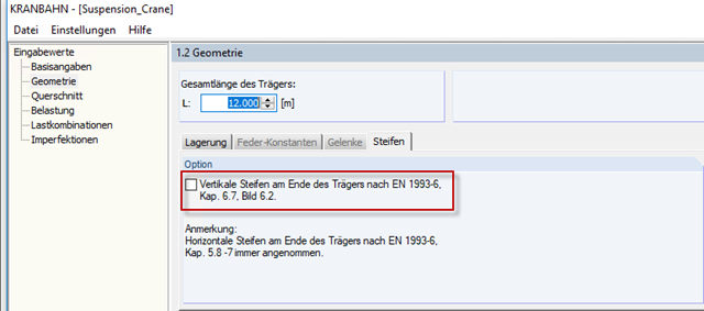
When defining the beam geometry in Window 1.2, the "vertical stiffeners at the end of the girder" option is activated by default in the "Stiffener" tab. Proceed as follows:
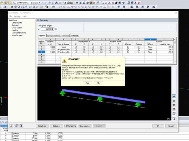
To determine the maximum support forces, it is often necessary to allow the crane to overrun the designed girder. This ensures that in case of asymmetric load distribution, for example, every wheel actually runs over the critical location of the girder.
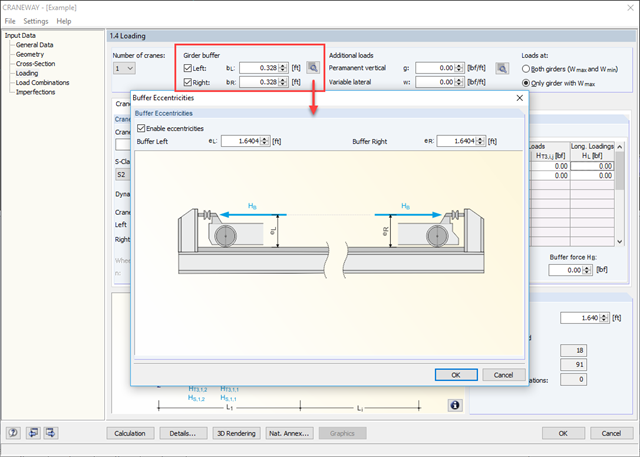
However, if there are girder buffers to prevent the crane from moving out on the left and/or right end, the distances bL and bR can be entered in both text boxes. This also reduces the number of generated load combinations.
If necessary, you can specify an eccentric arrangement of the buffers in a dialog box using the [Details] button (see image).
You can find more information about the design of craneway girders in the webinar under Links.